Model LV-24/20 LED Wall WasherEdition EN · 04 / 2026 · V1Dokument-Nr. LV2420-EN-01
IP65 LED Wall Washer · 6 Pixel Segments
LV-24/20
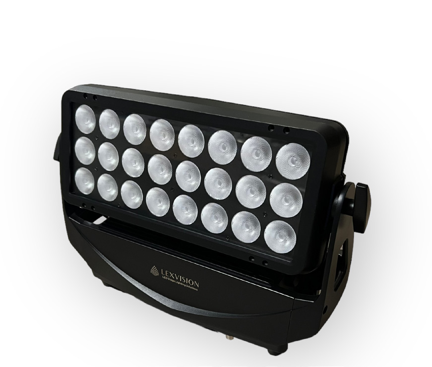
Weatherproof wall washer with 24 × 20 W RGBW 4-in-1 LEDs, six individually controllable segments, six channel modes and optional LumenRadio W-DMX
Operating manual. Please read in full before first use and keep for future reference.
Light source
24 × 20 WRGBW 4-in-1
Segments
6individually controllable
DMX channels
8–406 channel modes
IP rating
IP65Outdoor
Lexvision LV-24/20 Wall WasherForeword · About this document
Foreword
00Welcome
Thank you for choosing the Lexvision LV-24/20 — a weatherproof wall washer with 24 × 20 W RGBW 4-in-1 LEDs, six individually controllable segments and flicker-free operation for broadcast TV and film.
This document covers installation, operation, maintenance and configuration. Read the manual in full — especially the Safety Information chapter — before first use, and keep it with the unit.
0.1Intended Use
The LV-24/20 is a multi-environment luminaire with an IP65 rating, intended for professional use only and not suitable for household use. Permitted ambient temperature: −25 °C to 45 °C; all operating positions are permitted (device on floor or fixed to a support).
Lexvision LV-24/20 Wall Washer01 · Safety Information
Chapter 01
01Safety Information
Read this chapter in full before unpacking, installing, powering or operating this product. The fixture must be installed in accordance with the applicable installation code by a person familiar with the construction and operation of the fixture and the hazards involved.
Risk of Electric ShockAlways power off/unplug the fixture before removing any covers. Ensure that the power is turned off when connecting the fixture to the AC mains supply. Ensure that the fixture is electrically connected to earth. Do not apply power if the fixture is in any way damaged. Do not immerse the fixture in water or liquid.
Preventing Burns and Fire
Install in a location that prevents accidental contact with the fixture; install only in a well-ventilated space.
Install at least 0.3 m (12 in.) away from objects to be illuminated; ensure a minimum clearance of 0.1 m (4 in.) around the cooling fans.
Do not paint, cover or modify the fixture; keep all flammable materials away from the fixture.
Allow the fixture to cool for 15 minutes after operation before touching it. Exterior surface temperature after 5 min. operation = 45 °C, steady state = 60 °C.
Install only in accordance with applicable building codes.
Avoid Personal Injury
Do not look directly at the light source from close range.
Take precautions to prevent injury due to falls when working at height.
For permanent installation, ensure that the fixture is securely fastened to a load-bearing surface with suitable corrosion-resistant hardware.
For temporary installation with clamps, ensure that the quarter-turn fasteners are turned fully and secured with a suitable safety cable.The mounting point must safely bear the weight of the fixture; the fixture must additionally be secured with a suitable safety cable of sufficient load rating in accordance with local regulations and laws.
Active, forced air, temperature-regulated, with over-temperature protection
Housing
Aluminium, steel, PC/ASA plastic, rubber; PE lens, tempered glass front; black finish
Tilt
0° – 170°, manually adjustable
Installation
2 × quarter-turn fastening omega clamps · 1 × safety attachment point · two side handles on base
IP rating
IP65
Ambient temperature
−25 °C to 45 °C
Dimensions
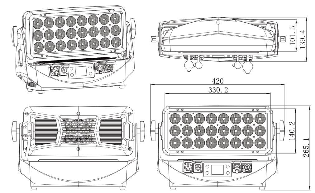
420 × 140 × 265 mm
Weight
6,6 kg net
Lexvision LV-24/20 Wall Washer03 · Parts Identification & Terminology
Chapter 03
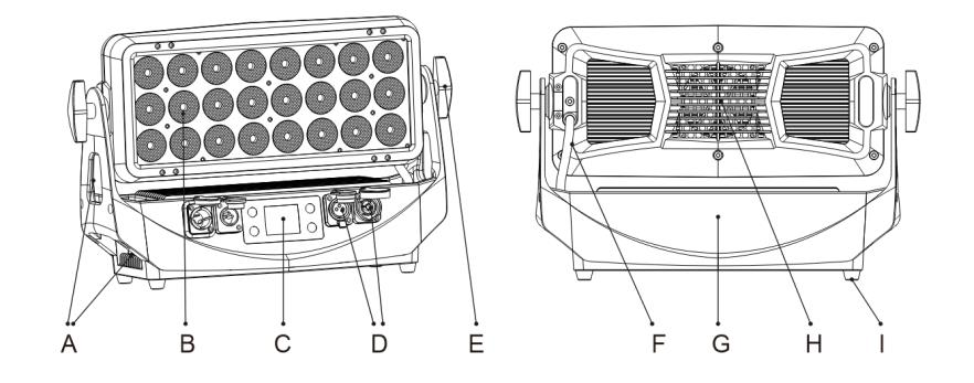
03Parts Identification & Terminology
Item
Description
A
Handle
B
24 × 20 W RGBW 4-in-1 LEDs
C
TFT LCD display control panel
D
Seetronic IP65 sockets
E
Tilt lock
F
Connection cable
G
Base
H
Cooling fan
I
Feet
Views with part identificationLexvision LV-24/20 Wall Washer04 · Installation & Mounting
Chapter 04
04Installation & Mounting
4.1Preparing for Installation
Unpack the fixture and inspect it for transport damage. The fixture is IP65-rated and designed for use in wet locations: protected against dust in quantities that would interfere with operation, and against low-pressure water jets from any direction. When selecting a location, ensure it is situated away from public thoroughfares and protected from contact with people, is not immersed in water or exposed to high-pressure water jets, and has adequate ventilation.
4.2Installation
The fixture may be installed in any orientation. If installed horizontally with a downward beam angle, water can pool in the fan wells — under normal operation the moisture evaporates. In locations with high rainfall, fabricate a rain shield above the fixture or change its position and orientation to minimise pooling.
Permanent installation on the ground: remove the rubber feet from the floor stand/base and fasten securely through the resulting holes with four corrosion-resistant mechanical fasteners suitable for the location.
Flown installation: remove the floor stand/base and rig the fixture to a support truss or structure using the two supplied quarter-turn brackets and suitable clamps.
The mounting point must safely bear the weight of the fixture; the fixture must additionally be secured with a suitable safety cable of sufficient load rating in accordance with local regulations and laws.
Adjusting tilt: loosen the two tilt screws (one on each side), tilt the fixture to the required angle (0° – 170°) and re-tighten the screws.
Safety Cable MandatoryAlways secure an elevated fixture with a safety cable as backup. If the fixture has been operating, always allow it to cool for 15 minutes before handling.
Lexvision LV-24/20 Wall Washer05 · Connecting AC Power
Chapter 05
05Connecting AC Power
The fixture can operate on any 100–240 V, 50/60 Hz AC mains power supply. It draws approximately 2 A at full power.
Permanent installation: have a qualified electrician wire the mains cable directly to a suitable branch circuit. The ingress protection (IP) rating of the junction must be suitable for the location.
Temporary installation: the mains cable may be fitted with a grounded connector intended for exterior use.
The fixture must be grounded/earthed and be able to be isolated from AC power. The AC power supply must incorporate a fuse or circuit breaker for fault protection.
5.1Number of Fixtures per Circuit Breaker
When installing standard type C circuit breakers there are no limitations due to the fixture in-rush current. Due to the nominal current of the fixture, ensure that no more than:
Circuit breaker
Maximum number of fixtures
Type C, 10 A
4
Type C, 16 A
7
No Dimmer SystemDo not open the fixture to replace the supplied power cable, or connect the fixture to an electrical dimmer system, as this can damage it.
After connecting the fixture to power, run the on-board test using the "Mode → Mode = Demo" menu to ensure that the fixture and each LED are functioning correctly.
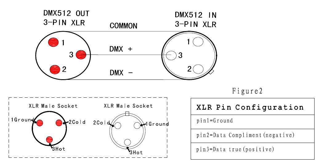
If using a cabled DMX system, connect the DMX in cable (male 3-pin XLR plug) and out cable (female 3-pin XLR plug) to the DMX data link. Pinout: pin 1 GND, pin 2 negative signal (−), pin 3 positive signal (+). Terminate the DMX out cable of the last fixture in the data link. For outdoor installations, use only IP-rated XLR connectors.
6.2DMX Start Address & Channel Mode
The DMX address is shown on the main screen. To change it, press the up arrow to increase or the down arrow to decrease the setting, then press Enter to save. Channel spacing is determined by the DMX mode, which you select in the "DMX mode" menu and confirm with Enter.
Example: if a fixture has address 10 and is in 8-channel mode, it uses channels 10 to 17. The next fixture in the chain can then be set to address 18. If two or more fixtures of the same type share an address, they will behave identically. Incorrect settings will result in unpredictable responses to the lighting controller.
6.3Master/Slave, Stand-Alone and Manual Operation
Master/Slave: configure one fixture as master via "Mode → Auto1 / Auto2 / Auto3 / Auto4"; further fixtures set to DMX mode act as slaves and mimic the master settings.
Static color: a predefined static color can be set via "Mode → Adjust" or the Manual menu — useful when no DMX controller is available for color mixing.
Stand-alone: four preprogrammed modes (Auto 1–4) play continuously in a loop; the run speed of Auto 1, Auto 2 and Auto 3 is adjustable.
DMX connector pinout
Lexvision LV-24/20 Wall Washer07 · Control Panel & Display
Chapter 07
07Control Panel & Display
7.1Buttons
Item
Button
Function
A
MENU
Select menu and return operations
B
ENTER
Enter menu and save operations
C
UP
Up select menu, increase value
D
DOWN
Down select menu, lower value
E
Display
1.77" TFT LCD display
7.2Display Indicators
Item
Meaning
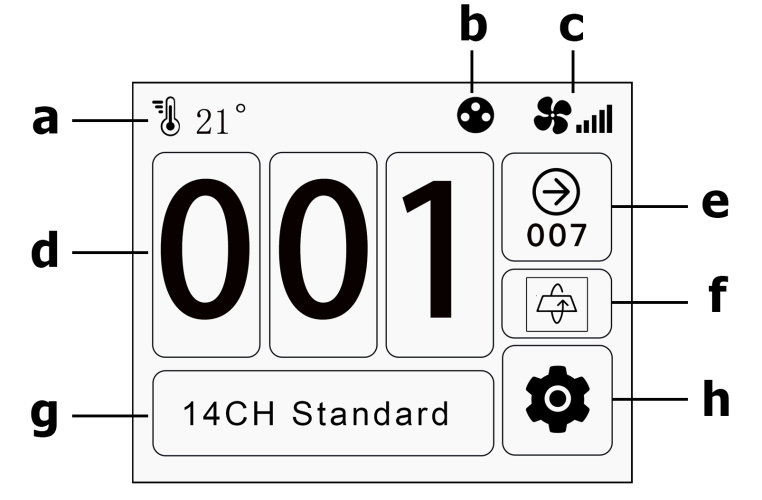
a
Temperature display
b
Signal status — red and flashing: no signal; always on: signal received
c
Fan speed status
d
DMX address
e
Automatically displays the DMX address of the next fixture
f
180 degree display flip
g
Channel mode
h
Settings (enter detailed menu)
Selection and UnlockingWhen a menu item is selected the icon displays yellow. After pressing the ENTER key the icon turns green, and only then can modification operations be performed. To unlock the screen, press the buttons in the prescribed sequence.
Display with control elementsLexvision LV-24/20 Wall Washer08 · Menu Structure
4CH RAW / 6CH RAW / 6CH / 8CH RAW / 9CH Strobe / 10CH CTC / 8*RGB / 27CH Strobe / 30CH Strobe / 32CH Strobe / 35CH RAW / 52CH / 21CH Studio / 3CH RGB / 4CH RAW / 6CH CTC / 8CH RAW / 10CH CTC / 31CH Standard / 43CH Extended / 22CH Studio
ConnectMode
ConnectMode
AUTO-D / WDMX-H / DMX-H / DMX
Operation
DMX / Pulse / Random / Jump / Fade
Fade
[000]
Jump
[000]
Random
[000]
Pulse
[000]
Manual
Dimmer
[000]
Strobe
[000]
Red / Green / Blue / White
each [000]
Dimming Curve
Square / Linear / S curve / I Square
Speed
[000]
Direct control without a DMX console
Display
Language
EN / 中文
Reverse
YES / NO
Backlight
YES / NO
Bright
Close 1 min / Close 10 sec / EverBright
Settings Led
L.U.R.U / R.D.L.D / L.D.R.D / R.U.L.U
Further settings
FanSet
AutoMation / LOWspeed / Highspeed
SignalHold
YES / NO
FactoryReset
YES / NO
Information
Fixture information
Version, operating hours, signal status
Factory
Password protected
The value tables in chapter 09 refer to the six C Channel modes. The manufacturer publishes no value tables for the G Channel modes.
Lexvision LV-24/20 Wall Washer09.1 · Channel Matrix — all six modes
Chapter 09
09DMX Channel Charts
9.1Channel Matrix — C Channel Modes
The matrix shows which channel number carries each function in each of the six modes. "—" means the function is not available in that mode. The full value ranges for the strobe, macro, control and pixel channels follow in chapters 9.2 to 9.5.
Function
8 CH
13 CH
16 CH
21 CH
25 CH
40 CH
Values
Dimmer
1
1
1
1
—
1
0 – 255
Dimmer fine
—
2
—
2
—
—
0 – 255
Strobe
2
3
2
3
—
2
→ 12.2
Strobe speed
—
—
3
4
—
3
0–7 —, 8–255
Macro
—
—
4
5
—
4
→ 12.3
Macro speed
—
—
5
6
—
5
0 – 255
Duration
—
—
6
7
—
6
0 – 255
Red
3
4
7
8
—
7
0 – 255
Red fine
—
5
—
9
—
—
0 – 255
Green
4
6
8
10
—
8
0 – 255
Green fine
—
7
—
11
—
—
0 – 255
Blue
5
8
9
12
—
9
0 – 255
Blue fine
—
9
—
13
—
—
0 – 255
White
6
10
10
14
—
10
0 – 255
White fine
—
11
—
15
—
—
0 – 255
Color temperature (CTC)
7
12
11
16
—
11
0–3 —, 4–255 CTC
Background red
—
—
12
17
—
12
0 – 255
Background green
—
—
13
18
—
13
0 – 255
Background blue
—
—
14
19
—
14
0 – 255
Background white
—
—
15
20
—
15
0 – 255
Control
8
13
16
21
25
16
→ 12.4
Pixel 1–6 (R/G/B/W)
—
—
—
—
1–24
17–40
→ 12.5
Mode names: 8CH Simple · 13CH Simple16 · 16CH Standard · 21CH Standard16 · 25CH 6*Pixel · 40CH Extended. The "16" modes (13 CH, 21 CH) add 16-bit fine channels; the 25-CH mode controls only the six pixel segments plus the control channel.
Lexvision LV-24/20 Wall Washer09.2 · Strobe — Value Ranges
Lexvision LV-24/20 Wall Washer09.3 · Macros — 23 Color Macros
9.3Macros
Channel position: 16 CH → channel 4 · 21 CH → channel 5 · 40 CH → channel 4. The run speed is controlled by the "macro speed" channel (16 CH → 5 · 21 CH → 6 · 40 CH → 5) and the hold time by the "duration" channel (16 CH → 6 · 21 CH → 7 · 40 CH → 6). The manufacturer labels the macros only as "Macro 1" through "Macro 23" — no description of the individual color sequences is published.
DMX value
Function
000–004
No function
005–009
Macro 1
010–014
Macro 2
015–019
Macro 3
020–024
Macro 4
025–029
Macro 5
030–034
Macro 6
035–039
Macro 7
040–044
Macro 8
045–049
Macro 9
050–054
Macro 10
055–059
Macro 11
060–064
Macro 12
DMX value
Function
065–069
Macro 13
070–074
Macro 14
075–079
Macro 15
080–084
Macro 16
085–089
Macro 17
090–094
Macro 18
095–099
Macro 19
100–104
Macro 20
105–109
Macro 21
110–114
Macro 22
115–119
Macro 23
120–245
Static pattern
246–255
Macro loop
Lexvision LV-24/20 Wall Washer09.4 · Control Channel
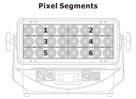
The six segments are addressed individually via channels 1–24 in the 25-CH mode (6*Pixel) and via channels 17–40 in the 40-CH mode (Extended). All pixel channels are linear from 000 to 255 (dark → bright). The direction of the pixel numbering can be changed via the control channel (pixel direction 1 to 4, see chapter 9.4).
Regular cleaning is essential to maintain optimal performance. Cleaning schedules vary depending on the operating environment.
Check the installation at frequent intervals within the first few weeks of operation to assess cleaning requirements in your particular situation.
Clean the fixture using a soft cloth dampened with a solution of water and a mild detergent.
Do not use products that contain solvents, abrasives or caustic agents, as they can cause damage to hardware, cables and connectors.
Check the fan wells for pooled water and contamination; keep ventilation openings clear.
Inspect seals and connectors regularly to maintain the IP65 rating.
WarrantyThe product leaves the factory in full working order and intact packing. Damage caused by misuse or by ignoring the warnings and this manual is not covered by the guarantee.
Lexvision LV-24/20 Wall Washer— · CE Compliance Notice
Appendix
—CE Compliance Notice
The manufacturer declares under its sole responsibility that the LV-24/20 complies with the relevant EU harmonization legislation.
EU Declaration of Conformity
A signed EU Declaration of Conformity exists for this product. It is not part of this manual and can be requested from us at any time — by email to verkauf@lexvision.de or by phone on +49 (0) 651 14567727, stating the product designation.
The signed EU Declaration of Conformity for this product is available upon request from Lexvision GmbH, Waldweg 26, 54636 Sefferweich, Germany.